Description
Operational Areas
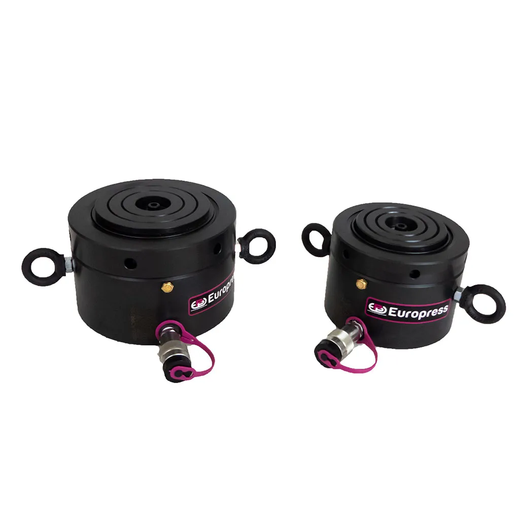
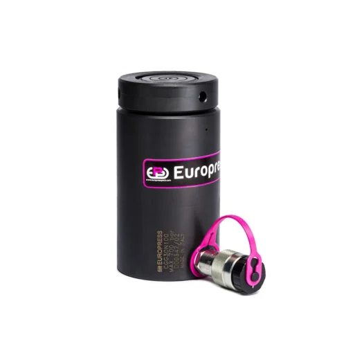
CGR cylinders are suggested in the construction and maintenance of bridges, viaducts, buildings, and industrial sites where the working space is limited. The protective nitriding treatment on these cylinders gives them excellent resistance to corrosion, making them suitable for use in adverse environments.
Accessories
-
Integrated tilt saddle, reduces the effects of possible off-centred loads.
CGR cylinders have been designed for use in applications where space is limited and to stand the full load even without a pressure distribution plate below. It is anyhow recommended that pressure plates are placed both under the base and on top of the saddle to distribute the load if the support resistance is not compatible with the pressure shown in the chart. Non compliance with this notice could result in damage to the cylinder and/or the load being lifted.
Although the standard tilt saddle allows to adjust the working load, it’s suggested to avoid any side components, especially if the cylinder has more than 20 mm of stroke.
During the lifting operation, the operator must always be in a position to observe when the coloured end of the section of the rod appears.
Selection Chart
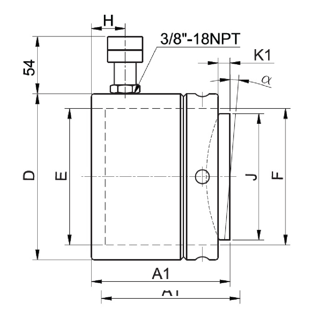
| PUSHING FORCE | STROKE | EFFECTIVE AREA | OIL VOLUME | CYLINDER BOTTOM PRESSURE | SADDLE PRESSURE | MODEL | CLOSED HEIGHT WITH INTEGRATED TILT SADDLE | Ø EXTERNAL | Ø PISTON | Ø ROD | ALTEZZA GIUNTO | Ø COUPLER HEIGHT | ROD PROJECTION WITH INTEGRATED TILT SADDLE | TILT SADDLE ANGLE | WEIGHT | * Nominal value, see kN for the exact force | |
| t* kN | mm | cm² | cm3 | mPA | MPa | A1 (mm) | D (mm) | E (mm) | F (mm) | H (mm) | J (mm) | K1 (mm) | a | kg | |||
| 60 606 | 50 | 86.6 | 433 | 39 | 100 | CGR60N50 | 125 | 140 | 105 | Tr 105×6 | 19 | 88 | 6 | 5° | 16 | ||
| 110 1078 | 154 | 770 | 46 | 113 | CGR110N50 | 137 | 178 | 140 | Tr 140×10 | 19 | 118 | 8 | 5° | 26 | |||
| 160 1589 | 227 | 1135 | 45 | 102 | CGR160N50 | 148 | 218 | 170 | Tr 170×10 | 19 | 148 | 9 | 5° | 42 | |||
| 200 1985 | 283.6 | 1418 | 45 | 87 | CGR200N50 | 154 | 242 | 190 | Tr 190×10 | 20 | 176 | 10 | 5° | 54 | |||
| 250 2424 | 346.3 | 1732 | 45 | 84 | CGR250N50 | 159 | 268 | 210 | Tr 210×10 | 22 | 196 | 11 | 5° | 68 | |||
| 400 4008 | 572.6 | 2863 | 44 | 89 | CGR400N50 | 178 | 347 | 270 | Tr 270×10 | 27 | 248 | 11 | 4° | 128 | |||
| 500 4948 | 706.9 | 3534 | 44 | 81 | CGR500N50 | 192 | 385 | 300 | Tr 300×10 | 30 | 285 | 10 | 3° | 171 | |||
| 700 6735 | 962.1 | 4811 | 44 | 85 | CGR700N50 | 200 | 445 | 350 | Tr 350×10 | 30 | 325 | 10 | 3° | 238 | |||
| 900 8796 | 1256.6 | 6283 | 47 | 83 | CGR900N50 | 216 | 495 | 400 | Tr 400×10 | 30 | 375 | 12 | 3° | 315 | |||

