Description
Operational Areas
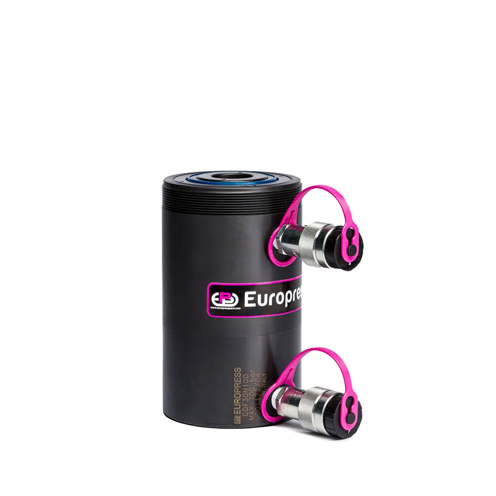
The through hole makes them particularly suitable for tensioning, mounting, and the extraction of pulleys, bushings, and heat exchanger pipes. They can be used in pushing and pulling operations by putting a bar or a cable attached to the saddle.
Accessories
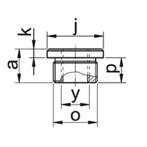
- ZTE threaded saddle allows the mounting of threaded bars.
Standard
- Smooth, hollow saddles avoid any risk of rod deformation.
Options
- L version, cylinders with aluminium body (COF###L###)
Selection Chart

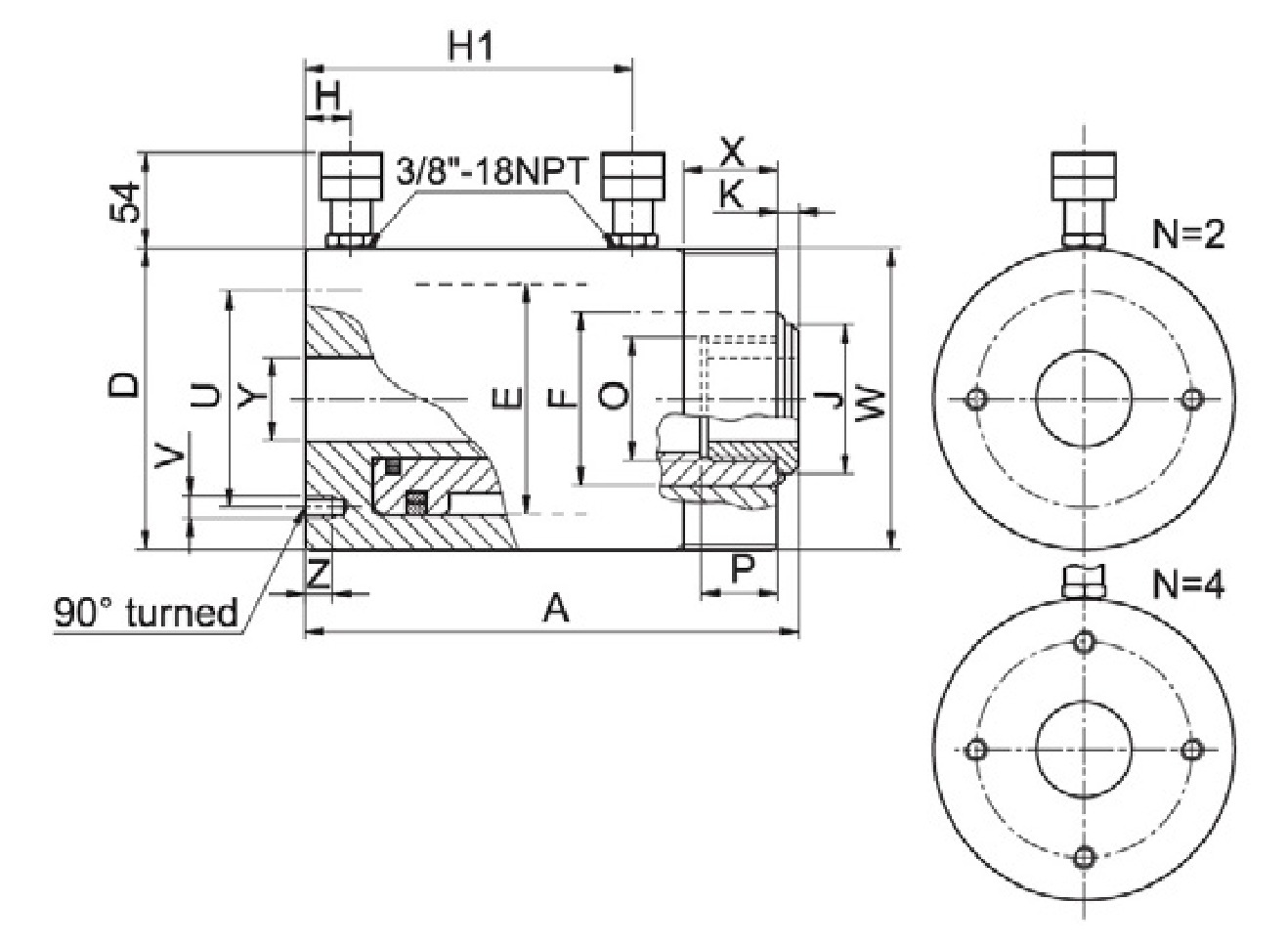
| PUSHING FORCE | PULLING FORCE | STROKE | PUSHINF EFFECTIVE AREA | PULLING EFFECTIVE AREA | PUSHING OIL VOLUME | PULLING IL VOLUME | MODEL | CLOSED HEIGHT | Ø EXTERNAL VERSION N Ø EXTERNAL VERSION L | Ø PISTON | Ø ROD | COUPLERS HEIGHT | Ø HOLLOW SADDLE | ROD PROJECTION | ROD INTERNAL THREAD | ROD THREAD DEPTH | Ø PCD MOUNTING HOLES | BASE MOUNTING HOLES DEPTH | COLLAR THREAD | COLLAR THREAD LENGHT | Ø THROUGH HOLE | WEIGHT VERSION N | WEIGHT VERSION L | * Nominal value, for precise capacity see kN | |
| t*kN | t*kN | mm | cm² | cm² | cm3 | cm3 | Amm | Dmm | Emm | Fmm | Hmm | H1mm | Jmm | Kmm | Omm | Pmm | Umm | V / Zmm | Wmm | Xmm | Ymm | kg | kg | ||
| 30 334 | 18 176 | 100 | 47.7 | 25.1 | 477 | 251 | COF30N100 | 196 | 115 125 | 90 | 70 | 21 | 152 | 57.5 | 2 | M48 x1.5 | 32 | 65 | 2xM1012 | M115x2 | 20 | 34 | 13 | 11 | |
| 150 | 716 | 377 | COF30N150 | 246 | 202 | 16 | 14 | ||||||||||||||||||
| 250 | 1193 | 628 | COF30N250 | 346 | 302 | 21 | 20 | ||||||||||||||||||
| 60 590 | 31 309 | 75 | 84.3 | 44.1 | 632 | 331 | COF60N75 | 186 | 165 180 | 125 | 100 | 26 | 134 | 81.5 | 2 | M72 x1.5 | 40 | 90 | 4xM1016 | M165x4 | 25 | 54.5 | 26 | 18 | |
| 100 | 842 | 442 | COF60N100 | 211 | 159 | 28 | 19 | ||||||||||||||||||
| 150 | 1264 | 663 | COF60N150 | 261 | 209 | 34 | 24 | ||||||||||||||||||
| 250 | 2106 | 1104 | COF60N250 | 361 | 309 | 46 | 32 | ||||||||||||||||||
| 100 947 | 58 568 | 75 | 135.3 | 81.1 | 1015 | 608 | COF100N75 | 214 | 215 235 | 165 | 130 | 36 | 155 | 17.5 | 4 | M102 x1.5 | 55 | 130 | 4xM1215 | M215x4 | 35 | 80.5 | 47 | 29 | |
| 150 | 2029 | 1216 | COF100N150 | 289 | 230 | 61 | 37 | ||||||||||||||||||
Accessories ZTE Threaded Saddles

| MODEL | FOR USE WITH | a | k | j | p | y | o | kg |
| ZTE30 | COF30 # # # # | 39 | 7 | 57.5 | 32 | 1 ¼’’ – 7 UNC | M48x1.5 | 0.3 |
| ZTE60 | COF60 # # # # | 47 | 7 | 81.5 | 40 | 1 ⅝’’ – 5 ½ UNS | M72x1.5 | 0.8 |

